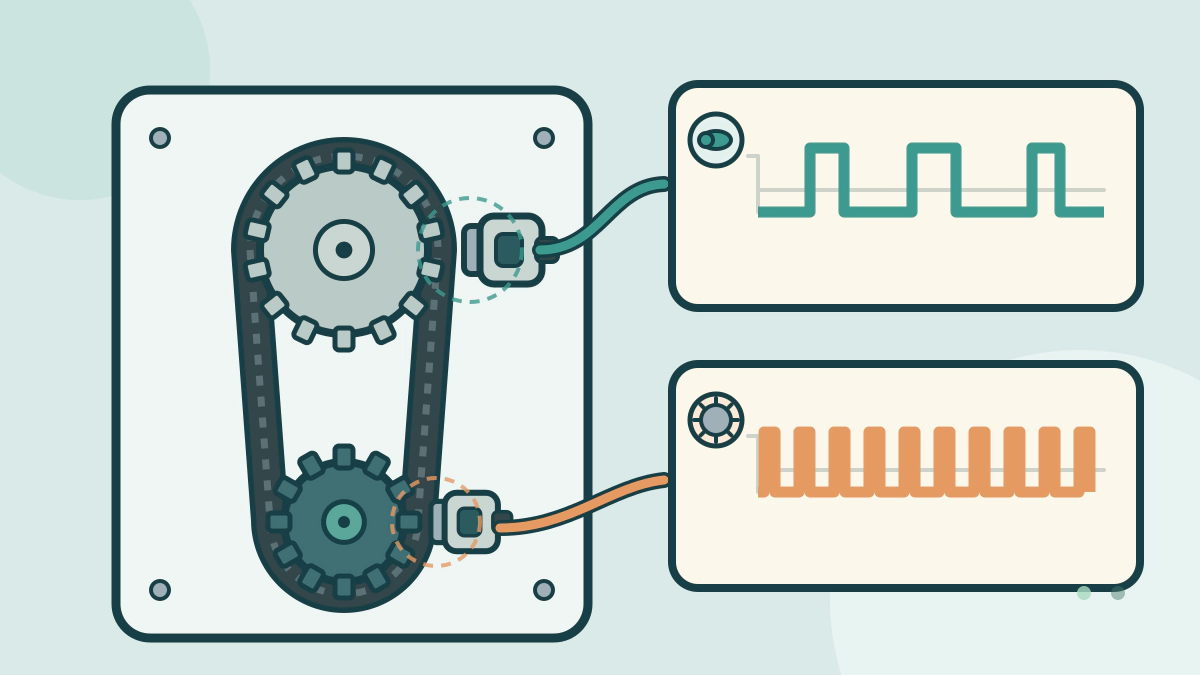
Learn what the crankshaft and camshaft position sensors each measure, why an engine needs both signals and how federal OBD rules treat cam-crank alignment.
What is the difference between a crankshaft and camshaft position sensor?
The crankshaft position sensor reports where the crankshaft is and how fast it turns; the camshaft position sensor reports the camshaft’s angle and which cylinder is on its firing stroke. They are separate parts that answer different questions for the engine control module.
DENSO describes the crank sensor as the source of crankshaft position and engine speed. The cam sensor adds the cylinder identity that a four-stroke engine needs. One cannot substitute for the other.
What the crankshaft position sensor measures
The crankshaft sensor sits on the engine block and faces a timing rotor on the crankshaft. As the rotor turns, its teeth pass the sensor. DENSO says the sensor counts those teeth and sends the count to the engine control module, which calculates where the crankshaft is within a 360-degree rotation. The rate at which that position changes is engine speed.
That makes the crank signal the main timing and speed reference. A missing crank signal can stop the engine from running at all.
What the camshaft position sensor adds
The camshaft sensor is mounted near the cylinder head, opposite a timing rotor on the camshaft. DENSO says it monitors the changing magnetic resistance from the moving rotor. The control module uses that signal to calculate the camshaft angle and to recognize which cylinder is firing.
Crank position alone tells the controller where the piston is, but not which stroke the cylinder is on. The cam signal resolves that ambiguity. It also gives the controller a way to check that the valvetrain is where the crank signal says it should be.
How the two signals compare
| Question | Crankshaft position sensor | Camshaft position sensor |
|---|---|---|
| What it watches | Timing rotor on the crankshaft | Timing rotor on the camshaft |
| Main signal to the control module | Crankshaft angle and engine speed | Camshaft angle and cylinder identity |
| Typical mounting area | Engine block, facing the crank rotor | Cylinder head area, facing the cam rotor |
| What the engine loses without it | Primary speed and crank-position input | Cylinder-phase information |
| Sensor designs | Inductive MPU or semiconductor MRE | Inductive MPU or semiconductor MRE |
DENSO lists both inductive MPU and magneto-resistive MRE designs. Connector shape, mounting depth and rotor pattern are engine-specific, so the parts are not interchangeable even when they look similar.
Why the engine controller compares them
Federal OBD rules for model year 2017 and later vehicles adopt California’s OBD-II requirements. The eCFR text includes a specific clarification: the requirement to verify proper alignment between the camshaft and crankshaft applies to vehicles equipped with variable valve timing.
That check requires both signals. A cam-crank correlation fault can point to a timing chain or belt that has moved, a variable-valve-timing problem, a damaged rotor or a mismatched sensor signal. It does not prove which part failed.
The Toyota repair manual parts location for the 2003 Camry Solara shows the crankshaft and camshaft position sensors as separate inputs to the engine control module. Locations and signal types vary by engine design.
What a missing signal can look like
A missing crank signal leaves the controller without the speed input it needs to schedule fuel and spark. Depending on the engine strategy, the result can be a crank with no start, a stall or a sudden loss of power. A missing cam signal leaves the controller unable to identify the cylinder phase. Some calibrations can continue in a default mode; others cannot.
Do not treat a no-start or a misfire as proof that a sensor has failed. A wiring fault, a poor ground, a damaged timing rotor, a jumped timing chain or a low battery can produce similar symptoms. The engine misfire guide explains why a misfire code can have many causes, and the no-start guide covers the checks that come before parts replacement.
How a technician sorts out the two sensors
Diagnosis starts with the fault code and freeze-frame data, not a guess. A technician compares the crank and cam signals on a scope or through live data and checks the circuit, connector, ground and rotor. DENSO warns that these sensors are delicate and must be kept free of moisture, chemicals and foreign material during installation.
If the engine uses variable valve timing, the cam-crank relationship may also depend on oil pressure and the timing components. The CAN bus guide explains how sensor messages reach the modules, and the Automotive Mechanical Systems hub covers the surrounding engine systems.
Replace a sensor only after the circuit and the mechanical timing have been checked. The owner’s manual and the manufacturer’s service information give the location, connector and test procedure for the exact engine.
Frequently asked questions
Are crankshaft and camshaft position sensors the same part?
No. They may use similar sensing technology, but they mount in different places, read different rotors and send different information. A crank sensor cannot report camshaft angle, and a cam sensor cannot replace the crank signal.
Can an engine run with a bad camshaft sensor?
Sometimes the controller can default to the crank signal, but not every calibration does. The service information states whether a default mode exists and what it affects.
Does the crankshaft sensor set ignition timing by itself?
It supplies crank position and speed. The controller calculates injection and ignition timing from it, the cam signal and other inputs such as airflow, throttle position and coolant temperature.
What causes a camshaft and crankshaft correlation fault?
Possible causes include a timing chain or belt that has skipped, a variable-valve-timing fault, a damaged timing rotor, a wiring problem or a sensor signal that does not match. The code identifies the circuit or relationship, not the failed part.